
This article is part of the GoldSim Style Guide. For an introduction, please start here.
Model organization is one of the most important aspects of your model. Without it, your readers will be lost, unable to make sense of how the model is set up. This can lead to many extra hours of time in debugging and making changes to the model. Because it is so easy to add elements to a model, if you don’t spend time organizing the model, you could end up with a large space of jumbled elements thrown across the graphics pane.
When you begin to design your model, you should always have in mind the audiences to whom you will be presenting or explaining the model. Most models will have at least two audiences:
- a high-level audience (managers and decision-makers who are primarily interested in the "big picture" or "bottom line"); and
- a low-level audience (analysts who are also interested in the technical details and assumptions of the model).
Often, there will be multiple low-level audiences, which are interested in different technical aspects of the model. There may also be a "mid-level" audience, which is interested in more than the "big picture” but does not want to get lost in the details. For a model to be successful (i.e., useful), you must be able to present and explain your model effectively to all these audiences.
One way to organize the model is as shown below. You can refer to this organization and modify it to fit your model’s requirements. This section will walk through some general guidelines for each of these categories.
- Dashboards
- Input Data
- System Model
- Use 1 localized container for each system component
- System Variables
- Results
- Testing
GoldSim provides the tools for you to create a single model that can be explained and presented to multiple audiences. The primary way in which you accomplish this is by organizing your model into a logical, top-down hierarchy.
By following the guidelines in this document and sticking with them as you continue building and maintaining your model, you should avoid problems and it will pay off in the long run.
Choose Appropriate Elements
Use elements that fit the context of what you are trying to accomplish. GoldSim provides a large set of various elements for a reason. While it might be possible to build most of your model’s logic simply using Expression elements, you should avoid doing this because the different types of elements provide visual context for the reader. For example, it is possible to use Expression elements for defining input data, IF statements, conditions and sums. You should instead use Data elements for data, Selectors for IF statements, And/Or/Not elements for conditions and Sum elements for sums, where possible. Below are examples showing what not to do compared to the recommended approach.
An example of using different GoldSim elements is shown below. In this example, simple Expression elements could have been used in the place of many of what you see. The specific GoldSim elements that are used below provide some insight into how the model works without even drilling into the specific expressions for each of these.
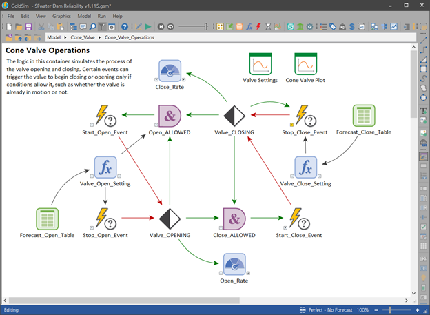
Try to avoid using the Expression element too much when other elements can do it much better. Below, I provide some examples of what elements are more appropriate than others. In general, you should learn about all the GoldSim elements and use your best judgment which ones are best for each occasion.
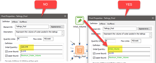
Data Element
Avoid inserting numeric values inside elements that are not Data elements. Use a Data element to hold the value then refer to it in your other elements as shown below.
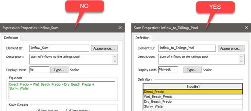
Sum Element
If you are summing outputs from multiple elements, choose the Sum instead of the Expression.
Material Delay Element
Material Delay elements are intended to be used to simulate delays in the physical movement (flow) of material. These delays often have a critical impact in the dynamic behavior of systems. Do not use an Information Delay or Previous Value element in its place if you intend to delay material flows.
Graphics Pane Layout
This section describes ideas for the style of the graphics pane, keeping in mind that it should be consistent throughout the model.
Flow of Logic
As a rule of thumb, try to organize elements within the graphics pane so that the reader can walk through the logic in a left to right and top to bottom direction. Below is an example of elements that follow this pattern of direction.

Dimensions
Try to fit everything within a consistent space for most containers of the model. One option is to fit everything in the container on a standard 8.5 x 11 size paper at 100% zoom in the graphics pane. A good rule of thumb is that you try to keep the total number of visible elements to 20 or less.
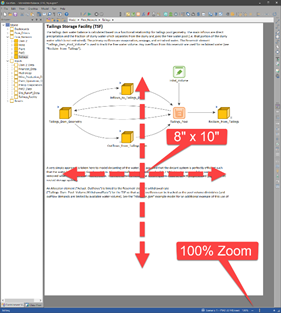
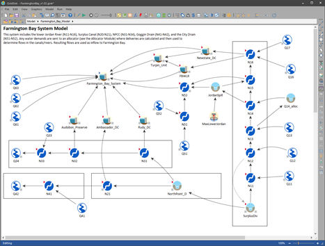
An exception can be made for a container showing a representation of a large system, especially when overlaid on a map image that requires the model elements appear smaller. In the example shown below, a larger area within the graphics pane is used to show all the nodes of a water system. Exceptions like these should be allowed to provide a schematic of the system being modelled. For most models, there will only be one Container with this exception.
If you want, you can explicitly define the bounds of the graphics pane with width and height values and apply these to all Containers. You can automatically apply these settings to all Containers by clicking the link at the bottom of the Graphics tab of the Container properties:
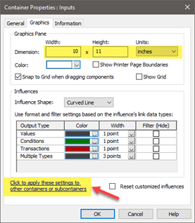
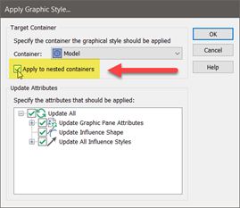
After clicking on this link, make sure you check the box to apply to nested (child) Containers.
This is one way to enforce that all elements are confined within a limited area that doesn’t require the reader to zoom out or pan around to see what is going on. If you find this method to be too restrictive for some Containers, you should make some exceptions to the rule but overall, this restriction will make the model more consistent and easier for everyone to read. It will also force you to divide the model up into smaller components that are easier to understand.
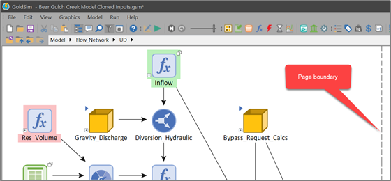
Alternatively, you can use Printer Page Boundaries instead of pane dimensions to guide you on the width to use. Below is a screen capture of an example model, showing how the documentation and elements fit within this default page width. Limit number of elements shown in a single Container (avoid requiring user to zoom out or scroll to see all elements).
Graphics Pane Orientation
The orientation of the working space of the graphics pane depends on how people will most likely read your model. If they do it with the model open on ½ of a computer screen (either right or left half), then a portrait orientation should work best. Otherwise, a landscape orientation is best.
Graphics Pane Zoom
Zoom should generally be 100% for the entire model.
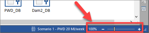
It may be tempting to reduce the zoom level on the graphics pane to accommodating a growing number of elements being added due to more complex logic. But this approach will lead to a model that is inconsistent and more difficult to read. As the complexity grows, you should use GoldSim’s Containers to further encapsulate parts of the model. This way, people reading the model can view a single page without becoming overwhelmed.
Background Color
The background color of the graphics pane should be white. This provides the best contrast for other colors and images used.
Using Containers
Perhaps the most important requirement of a well-documented and easily understood model is that it be well-organized. Containers provide the mechanism in GoldSim by which you can create well-organized models. In most cases, you do this by placing model elements in a “top-down” containment hierarchy in which the level of detail increases as you "push down" into the hierarchy.
In a well-organized model, you can imagine that each Container has a specific "message" and a corresponding audience at which it is targeted. For example, a model's highest-level Container might have the following message: "This is the problem I am trying to solve, and here is the overall structure of the model I have built to solve it". Such a Container would be intended for all audiences.
Another Container's message in the model might be "Here are the detailed assumptions regarding process X". This Container's audience would be the analysts or technical personnel interested in that aspect of the model.
You "hide" these details in a Container, because they are of no interest to higher level audiences (e.g., managers). Those who are interested, however, can be shown the contents of the Container.
Localized Containers
In most models, element names are forced to be unique. In some cases, however, you may want to have more than one element with the same name. This requirement usually arises when you have several similar subsystems in your model.
For example, suppose that you have developed a subsystem (within a Container) that calculates the balance in a bank account as a function of the previous balance, interest rate, deposits and withdrawals. Each of these items would be represented by its own element in the Container. After creating these elements, you decide you would like to track ten other accounts.
In such a case, it would be convenient to create ten copies of the Container (one for each of the other ten accounts). If GoldSim allowed you to just make copies of the bank account Container, however, there would be confusion when you referred to an element by name (e.g., in an expression), since GoldSim would have no way of knowing which copy of the element you were referring to.
GoldSim’s solution to this problem is to allow you to localize portions of your model, such that any element names in the local region are hidden from elements outside of that region. A local region is referred to as a “scope” in GoldSim. Elements with the same name cannot exist within the same scope. Elements can, however, have the same name if they are in different scopes. You change the scope of an element by localizing the Container in which it is located. Unless you specifically “expose” an element, the contents of a local Container can only be "seen" and hence referenced by other elements inside the Container.
Input Data
It is recommend that all the input data in the model be either be organized into a single folder at the top level of the model (called, for example, “Input_Data”) or within the components of the model where they are being used. Below is a screen capture of a model with the input data being saved at the top level in the “Input_Data” container.
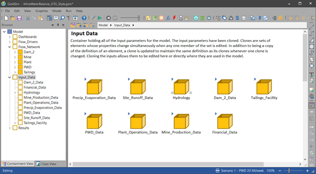
Note that input data may consist of Data elements, Stochastics, Lookup Tables and Time Series.
For models with fewer inputs, you might consider cloning the inputs to both the top-level Input_Data folder and the components of the system. Refer to the “Cloning Input Data” sub-section for more information on how to do this.
Globals
In some cases, you may want to define global properties that can be referenced throughout your model. One way to do this is to simply define Data elements at the global level of the model (i.e., outside of any localized Containers). GoldSim also provides a more convenient way to do this via the Globals tab of the Simulation Settings dialog. This is a good way to define model constants because these cannot reference other outputs of the model.
Once you have added a Global property, you can subsequently reference the variable by using the specified Name that you defined previously, preceded by a ~. For example, if you create a Global called X, you could reference it in input fields anywhere within the model as ~X.
Organizing Input Data
There are 2 ways to organize the input data at the global level:
- Organized by subject
- Organized by type of data
Organizing by subject allows the reader to browse based on the components and subjects of the model while the latter will provide a way to view the types separately. The latter approach is preferred for large models because it is often helpful to group elements that read data from external files in a similar way. For example, it might be helpful to import time series data into your Time Series elements. It would be nice to have these all in one place in case you need to make a change to the import process.
If you decided to clone the inputs into the individual containers for the system, then it would make sense to organize the inputs by data type since you can always browse through the system model and find their clone. Some examples of input data categories that might be useful (and are suggested) include:
- Constants
- Key_Assumptions
- Optimization_Variables
- Scenario_Data
- Time Series
- Stochastic_Input
- Test_Data
This list is not exhaustive but intended to provide you with ideas for your model.
Cloning Input Data
Cloning Data elements (and other inputs such as Stochastics, Lookup Tables and Time Series) to other places in the model helps the reader understand how they are being used without having to navigate back and forth between the system model and the inputs Container. If you don’t have a lot of input data in your model, then this approach might be appropriate (since a cloned element requires the same amount of memory as a copy of an element).
You create clones of an element by right-clicking on the element you wish to clone in the graphics pane or a browser to access its context menu, and selecting “Clone Element”. When you do so, you will then be presented with a dialog containing all the Containers in your model. Using this dialog, you must then select the Container into which you wish to place the clone. If you select a Container in a different scope, the cloned element will have the same name as the element being cloned. All clones are "equal". That is, the original element is no different than the clone which was created from it. Both are clones, and if you change an input to one, the same input in the other is automatically changed accordingly.
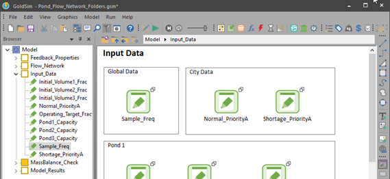
The benefit of organizing the model this way is that we can work with all the data in multiple places.
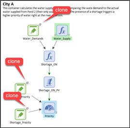
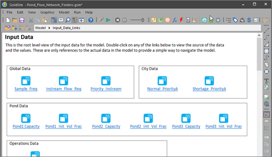
Below is a view of the input data all Contained in the Input_Data Container. Note again the symbols indicating clones. In most large models, the input data needs to be further organized into child Containers. Localizing these child Containers is recommended.
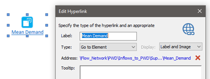
Note: Scenario data cannot be cloned so you will need to use a Hyperlink in its place. Set the Type to “Go to Element” so that when you double-click on the Hyperlink, you jump directly to the scenario data.
Hyperlinks to Input Data
An alternative to cloning all input data is to use Hyperlinks that jump to the data from the top level. This is applicable to larger models that use a large amount of input data since a cloned element requires the same amount of memory as a copy of an element.
System Model
The purpose of building a model is to represent a physical system that changes over time. Most often, this system will take the shape of a network of interconnected components. It is often useful to organize the model in such a way that provides a visual representation of this system. You can do this by building components of the system inside a parent container that represents the system you are modeling. This parent Container is the “System” Container of your model.
Even though the name “System” is used in this style guide, the actual name used is not important. Choose a name that works best for your model. Each of the nodes within the system can be made up of a single element or (most often) a localized Container. If you use Containers to represent system components, they should be localized so that you can take advantage of their object-oriented nature.
Below is a screen capture of the contents of an example System Container, showing the child Containers inside that represent the components of the system and their physical interactions. You can download a copy of this model by clicking the link at the bottom of this article.
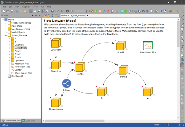
Within each node (Container) of the system, you can reference input data, variables within the node, and outputs from other sibling nodes in the system.
Information References
Sometimes attributes of a system component are used in another component to influence behavior. This kind of influence is referred to as information. It is very common in a system model to have many information-type influences and it will quickly make it harder to understand how material flows are represented by just looking at the influence lines. If you want to improve the visual representation of material flows, then you should re-route the influences to pass through a parent Container (outside the System Model Container). If you feel this type of influence line filtering is unnecessary for your model, feel free to skip it.
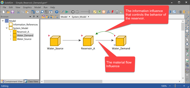
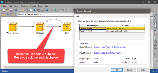
To give you a better understanding of the difference between material flows and information influences, consider the simple example of a supply-demand model, shown in the screen capture below. In this model, there are 2 influence lines connecting the Containers “Reservoir_A” and “Water_Demand”. One of the influences represents the material flow from the reservoir to the water demand. The other influence line doesn’t represent water flowing but instead the information used to control the flow from the reservoir.
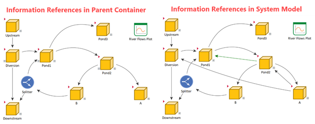
It can be difficult to visualize the flow paths at the system level (of complex models) because of additional influence lines that represent model logic. To create a clearer visual representation, it is recommended that you use parent-level references to filter out the information type influence lines. This is done by referring to information outputs in a parent Container (located outside the System Container) then refer to these external references in expressions within the system. This approach is better than manually changing the colors of the influence lines because this model structure improves the overall organization of the model as well. The goal is to provide the reader with a clear view of the material flows between system components. Keep in mind that material flows are not limited to water. Your model could be simulating flows of solids, money, people, or items.
Identifying Information Influences
The first step in organizing a model with a focus on material flows is to identify the influences that are information only. If you double-click on an influence line, a list of outputs will be displayed, showing you all outputs that are being referenced. In the case of the example model shown below, it shows the discharge rate and volume of the reservoir that is being referenced inside the City component.
Walk through all the outputs of influence lines in your system model by clicking on each one. As you do so, make note of those outputs that are information only and not referencing a material flow. You will end up with a list of information references.
Organizing Information References
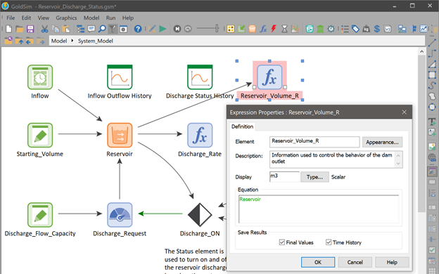
Now that we have identified the information type influence, we can create a reference to the information using an Expression element and give it a name that resembles its special job of being a reference. In the example below, an Expression element is used with a name that ends in the letters “R” and highlighted with a red fill color. This element is doing nothing more than referring to the information output of an element in the System_Model.
Move this reference element to a new container called “Information_References” then move the remaining elements into another new container called “System_Model”. The top level of the model should now be organized into 2 Containers as shown below.
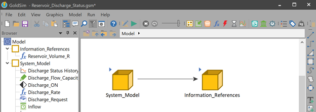
The contents of the System_Model Container should be further organized into the physical components being represented. For large models, this step is an important part of model construction.
Using Information References
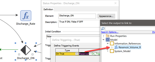
After you move the information reference to the Information_References Container, you should change the element in the System_Model to refer to the external reference instead. In the example shown below, the Status element is currently referring to the Reservoir volume, which causes it to change state during the simulation. This is the element we must change so that it points instead to our external information reference. This will cause the influence line to disappear from the System_Model Container since it is now being referenced in the parent level.
In the examples shown below, showing the graphics pane of the System_Model Container, because the information influences have been filtered out, the only influences remaining represent water flowing through the network. This approach can significantly improve the readability of your system model, particularly for complex material flow systems.
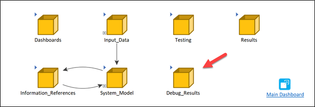
Model Results
A good way to organize summary results for the model is to place them in a top-level Container called “Model_Results”. In most cases, it is helpful to organize Result elements into a central location just like you do for the input data so that a user can walk through all the results at once instead of navigating to all the components. A central Container for results also makes it easier to walk through, browse, or search for specific results without having to understand the details of the system.
It can also be very helpful to create a temporary Container to store Result elements that are used only for debugging. These are where you store results that help you build the model. If you save these in a separate Container of the model, then removing and disabling unnecessary results at the time of production is a lot easier.
Element Fill Colors
Element fill colors can be used to highlight certain roles of elements. Examples of these roles might be signaling a later revision to an expression or refer to outside influences.
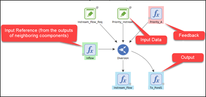
The example shown below uses an example color scheme to highlight some elements. The example below uses yellow fill for elements that are a work in progress and require the modeler to revisit later for possible revision. Green is used for elements that reference outputs from sibling nodes within the System Container (such as a flow from another component of the system). Elements that provide an output used by other sibling nodes are filled with a blue color. The blue and green colors will give the reader a quick overview of where information is coming from and where it is going.
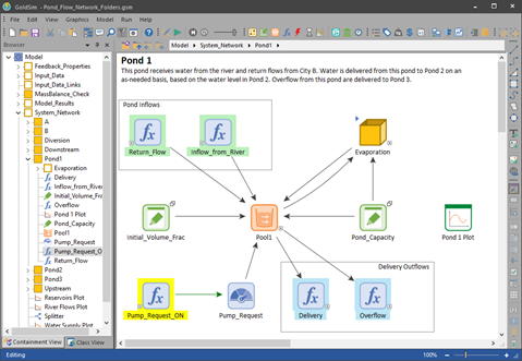
Use bright colors to highlight elements that require revisions so that others will easily see these in the future. Use colors that are not too distracting for other references that are intended to be permanent like for references to inputs and outputs. Table 1 summarizes some color suggestions that you can use in your model, which can be modified to better suit your specific requirements.
Table 1 – Color Suggestions for Highlighting Special Features of Elements
|
Special Feature |
Color |
|
Work in progress |
|
|
Input reference from the outside |
|
|
Output being referenced to the outside |
|
|
Information References |
|
The result is a graphics pane that shows you upon viewing just the colors, where information is coming from and where it is going. The only elements not marked are the local functions used to carry out the process done by the object this container represents.
If you use element fill colors this way, it is recommended that you place a legend in the documentation of the model to remind the reader of the meaning of each color.
Download an Example Model used to show the examples described above.
Comments
0 comments
Please sign in to leave a comment.